
OpenGL 3: The Matrix
So far we’ve only been dealing with positions in Normalized Device Coordinates (NDC) so in this chapter we’re going to enter the matricies. We’ll be diving into OpenTK’s Mathmatics library to explore what and why we use matricies as well as checking in on some of the other types.
Using these matricies we’ll be able to transform our plane old triangle into a fully three dimensional cube and place it anywhere we want. Don’t worry there’s no advanced maths in here - I’ll be leaving the explaining of why the maths we use works to people far smarter than me.
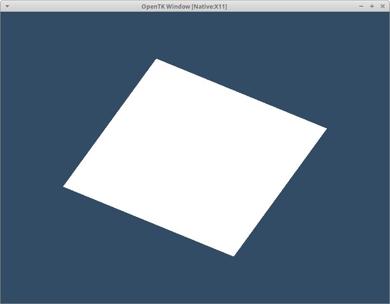
As usual lets take a look at what we’re working towards:
Cubular
As awesome as our quad is it won’t do a good job showing off our 3D world. We’ll fix that by upgrading it to a cube.
Vector3[] verticies = [
    (-0.5f, -0.5f, -0.5f), (0.5f, -0.5f, -0.5f),(0.5f,  0.5f, -0.5f),
    (0.5f,  0.5f, -0.5f), (-0.5f,  0.5f, -0.5f),(-0.5f, -0.5f, -0.5f),

    (-0.5f, -0.5f,  0.5f), (0.5f, -0.5f,  0.5f),(0.5f,  0.5f,  0.5f),
    (0.5f,  0.5f,  0.5f), (-0.5f,  0.5f,  0.5f),(-0.5f, -0.5f,  0.5f),

    (-0.5f,  0.5f,  0.5f), (-0.5f,  0.5f, -0.5f),(-0.5f, -0.5f, -0.5f),
    (-0.5f, -0.5f, -0.5f), (-0.5f, -0.5f,  0.5f),(-0.5f,  0.5f,  0.5f),

    (0.5f,  0.5f,  0.5f), (0.5f,  0.5f, -0.5f),(0.5f, -0.5f, -0.5f),
    (0.5f, -0.5f, -0.5f), (0.5f, -0.5f,  0.5f),(0.5f,  0.5f,  0.5f),

    (-0.5f, -0.5f, -0.5f), (0.5f, -0.5f, -0.5f),(0.5f, -0.5f,  0.5f),
    (0.5f, -0.5f,  0.5f), (-0.5f, -0.5f,  0.5f),(-0.5f, -0.5f, -0.5f),

    (-0.5f,  0.5f, -0.5f), (0.5f,  0.5f, -0.5f),(0.5f,  0.5f,  0.5f),
    (0.5f,  0.5f,  0.5f), (-0.5f,  0.5f,  0.5f),(-0.5f,  0.5f, -0.5f),
];
Replace your verticies with these fresh out of the oven ones and oh it’s still just a quad. When you look at a cube head on without any form of perspective you can’t see the sides. In order to create some perspective we’ll need one of our titular matricies.
Engage 4x4
A Matrix is a 2D array of numbers with a defined size. The defined size can be anything and if you look through the OpenTK.Mathematics namespace you’ll find a plethora of sizes from 2x2, 3x2 or 4x3 all the way up to 4x4. Every size also includes a complementary double variant should you ever find yourself working with those.
It’s worth looking at System.Numerics at this point as well and compare their Matrix4x4 with OpenTK’s. While you’re there you will notice there’s a Matrix3x3 alongside and nothing else. The wide range of types available in OpenTK.Mathmatics are just one of the many reasons to use the library. It’s even available as it’s own Nuget Package if you just want to crunch some numbers.
With all that said why exactly do we need to use a matrix in the first place? There’s two jobs we need to do that they make incredibly simple. First being converting between coordinate systems and second applying transformations to coordinates. You might be thinking “those are the same” and you’re not wrong but we will be doing these two separately in code so it’s helpful to think of them this way.
That’s enough talking about the solution lets get to work implementing it! We’re going to start with the second use case as that’s going to give us immediate feedback. We want to see more than just one side of our cube so a rotation seems like a good place to start. The typical approach to using types in C# is to new one up and go from there however (and it’s a big however) this is the worst thing you can do with a Matrix4.
Matrix4 useless = new Matrix4();
/*
0, 0, 0, 0
0, 0, 0, 0
0, 0, 0, 0
0, 0, 0, 0
*/
It might seem harsh but a new Matrix4() returns one filled with 0 which turns out to mean absolutely nothing. If we used this empty matrix to do any calculations it would turn everything it touched into meaningless number soup. Instead whenever we start with a fresh matrix you need to use a predefined one called the Identity. The Identity Matrix isn’t a film but one with a diagonal fill of 1. We can find this as a static property on the class:
Matrix4 useful = Matrix4.Identity;
/*
1, 0, 0, 0
0, 1, 0, 0
0, 0, 1, 0
0, 0, 0, 1
*/
Did you see all the other properties and fields on the class? This is the primrary way of constructing new matricies and I could even go as far as to say if you use new Matrix4() you are making a mistake. Armed with this knowledge can you find how to start a rotation? If you found Matrix4.CreateRotationX congratulations! It only takes one argument for the amount of rotation to create but there’s a catch. This rotation MUST be in radians.
Radians are an angle measurement based around Pi where a full circle has 2 Pi worth of Radians in contrast to Degrees where a full circle has 360 of them. Every angle we use is going to be in Radians and it’s something you should get comfortable with as quickly as possible. Now that you’re 100% onboard the radian train we can create our rotation matrix:
Matrix4 rotation = Matrix4.CreateRotationZ(0.5f);
/*
0.87758255, -0.47942555, 0, 0
0.47942555, 0.87758255, 0, 0
0, 0, 1, 0
0, 0, 0, 1
*/
Those sure are some numbers. We’ll look at how to combine rotations later on for now we want to apply this rotation to our cube.
So Very Uniform
So far we’ve only sent information to the GPU in the form of the Vertex Array. We could pack our rotation matrix into this array as well but unlike the verticies the rotation data is going to change. Not just a change every so often either we’ll be changing the rotation every frame later on. Thankfully OpenGL has another way to send data over that’s a perfect fit for us: Uniforms.
The name Uniform comes from the value remaining consant, i.e. uniform, throught the shader pipeline. This is in contrast to all the other values that get passed between shaders which do change step by step. As you will come to expect Uniforms need two parts to work correctly: a shader declaration and a method to populate them. We’ll start on the shader side and head back to our Vertex Shader:
#version 330

in vec3 position;
uniform mat4 rotation;	//here’s the new uniform

void main ()
{
    gl_Position = vec4(position, 1.0) * rotation;
}
GLSL is still running short on letters so the corresponding type is mat4 along with mat3x4 and so on. We declare our Uniform using the uniform qualifier instead of in. I’m going to skip over what’s going on with the rotation value for now to cover the CPU side instead.
To send a uniform value to a shader we use one of the many GL.UniformXY methods. This is one of the changes in OpenTK 5 which stopped providing generic overloads and keeps the original C method names. The X part of the method name is for the structure being sent which is Matrix4. After this comes the Y part to indicate the type of data being sent which is f for float. This pattern makes it fairly easy to find the right method and is used throughout OpenGL’s API; there’s no Vector3 methods these are just 3f so Vector3d becomes Uniform3d and following that a single float is Uniform1f.
Before we dive fully into UniformMatrix4f the first argument asks for a uniform value and we don’t have one yet. This is a similar process to VAO Attributes but thankfully a lot easier. Once a shader is compiled we can ask OpenGL if it contains a named uniform and receive the uniform location. We do this with GL.GetUniformLocation and pass in our shader Id and ”rotation”.
// setup code

// … previous vertex attribute stuff

int uniform = GL.GetUniformLocation(shader.Id, “rotation”);
We’d get back -1 if no uniform was found with that name. If you’ve missed the second change to the vertex shader this might be the value you get back now. Why does that happen even when the uniform is declared? OpenGL allows the driver to AGRESSIVELY remove unused uniforms and they typically will. We won’t deal with this happening but it’s something to keep in mind when developing and there are plenty of ways to work with it.
With our uniform value hopefully populated with a valid location we can carry on with UniformMatrix4f:
// loop code
GL.Clear(ClearBufferMask.ColorBufferBit);

GL.UniformMatrix4f(uniform, 1, true, rotation);

GL.DrawArrays(PrimitiveType.Triangles, 0, verticies.Length);
After the uniform value comes a count for how many values are being sent. At first you might think this is excessive as only one value is being sent but the original C API only requires a pointer which could be to any amount of data. Next is transpose which has an entire section dedicated to it coming up after this one. Finally is our value which is the rotation matrix we cooked up earlier.
Major Fights
There’s an unavoidable topic when it comes to using a Matrix in programming: how do you store the data? We usually look at matricies as a theoretical 4x4 array where the data just exists. Unfortunately computers are not big fans of theoretical data and need it represented exactly!
To do this we need to take the values and store then in an array. The question then is what order do values occur within this array? Lets take a look at an actual matrix full of unique values so we can keep track of them:
 0,  1,  2,  3,
 4,  5,  6,  7,
 8,  9, 10, 11,
12, 13, 14, 15
Everyone agrees that we should start populating our array with the 0,0 value, that’s 0:
[ 0, …? ]
Next we need to make a choice: do we go horizontally or vertically? Is it [0, 1, … ] or [0, 4, … ]? It turns out both options are valid which is just the worst. As this discussion occurs quite frequently there are names for both options. Going row by row is called Row Major and column by column is Column Major. These names are so descriptive and useful that I doubt anyone involved in programming came up with them. For an extremely in-depth look at the two there’s a great Scratch A Pixel Lesson.
// Row Major
[0, 1, 2, 3, 4, 5, 6, 7 … ]

// Column Major
[0, 4, 8, 12, 1, 5, 9, 13 … ]
Now we’ve discovered there are two options why does it matter? All systems must agree on the order data is read in and with both System.Numerics and OpenTK.Mathmatics using Row Major we transpose them on the way to OpenGL. As a result we set transpose: true whenever setting any Matrix value via a uniform.
When you read C++ code you will probably see the transpose value is set to false or GL_FALSE. Are they making a mistake? The complete answer is much more complicated but the short one is No. Along with the Major convention there is also a Left/Right Multiplication convention. This describes if you want vector * matrix or matrix * vector to give the correct result. Both will always compile which is why this causes so much trouble!
OpenTK chooses Left Multiplication so our code reads vector * matrix and so our GLSL goes:
// Left Multiplication
gl_Position = vec4(position, 1.0) * rotation * projection;
When you read C++ tutorials they are using Right Multiplication so their code reads matrix * vector and so their GLSL goes:
// Right Multiplication
gl_Position = projection * rotation * vec4(position, 1.0);
The big takeaway from this is you must be aware of the matrix conventions when reading other code. Typically this means reversing the order of any vector * matrix multiplication but not always!
Get Rotated
Having our cube sit at a jaunty angle has already lost its appeal so lets get moving. We’ll be using the power of uniforms to change the value every frame and finally bring the whole thing together. We’ll avoid changing the rotation matrix and update the input angle instead. To do that add a angle float to the end of our setup then we can increment it inside the loop.
// end of setup code
float angle = 0f;

while (true)
{
    Toolkit.Window.ProcessEvents(false);
    if(Toolkit.Window.IsWindowDestroyed(window)) break;

    // loop code
    GL.Clear(ClearBufferMask.ColorBufferBit);
    Matrix4 rotation = Matrix4.CreateRotationZ(angle);
    GL.UniformMatrix4f(uniform, 1, true, rotation);

    angle += 0.01f;

    GL.DrawArrays(PrimitiveType.Triangles, 0, verticies.Length);

    Toolkit.OpenGL.SwapBuffers(context);
}
We use quite a small value when increasing the angle each frame as we update at least 60 times a second, more if you have a higher refresh rate screen, and the input range is from 0 to 3.14ish. AlthoughCreateRotation` graciously handles it for us we should really be using values within that range. Luckily there’s a function in OpenTK that does exactly that:
angle += 0.01f;
angle = MathHelper.ClampRadians(angle);
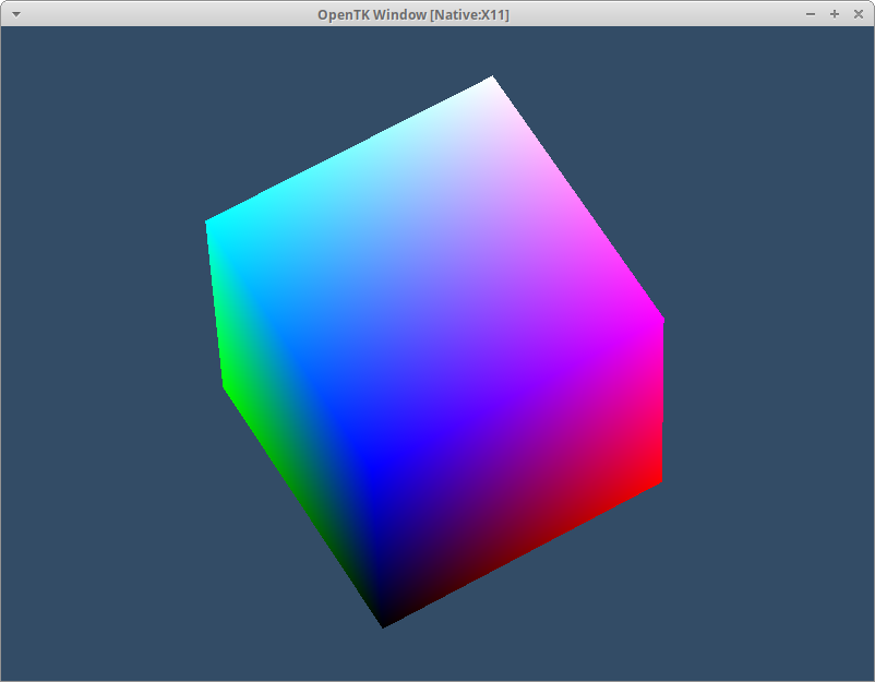
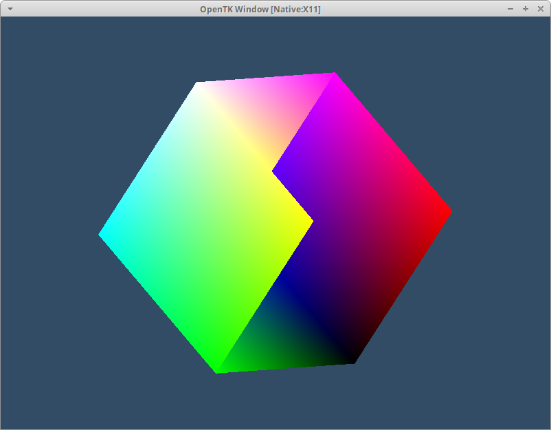
So far we’ve been rotating about the Z axis. Try rotating about the other ones and what do you see? About the Y axis it only appears to grow taller and skinner and about X it doesn’t seem to be moving at all. This is because our entire cube is pure white - there’s nothing to see rotating. We can quickly bring some colour to our cube by abusing the vertex data. Head back to our Vertex Shader code add a out value next to our existing variables. This will be a vec3 and we can call it color. You’ll then need a matching in value in the Fragment Shader which we can then use for our fragColor. I’ll add a flat 0.5 to the position to lift all the negative values out of being pure black and make it a little more interesting to look at.
#version 330

in vec3 position;
out vec3 color;
uniform mat4 rotation;

void main ()
{
    color = position + vec3(0.5);
    gl_Position = vec4(position, 1.0) * rotation;
}
#version 330

in vec3 color;
out vec4 fragColor;

void main ()
{
    fragColor = vec4(color, 1.0);
}
Remember the output of the Fragment Shader needs to be a vec4 so don’t forget to expand it! With our shader code updated we should now see a wonderfully colourfull cube:
For our final trick we’re going to combine all three rotations at once. Were you paying attention to the previous section? I don’t blame you if not so a quick reminder: matricies are combined with multiplication. We can combine them like so:
Matrix4 rotation = Matrix4.CreateRotationY(angle)
    * Matrix4.CreateRotationX(-angle)
    * Matrix4.CreateRotationY(angle / 2f);
Mix up the values for yourself and see how they change. Once you’re done having fun we’ll look at why it looks a bit funky sometimes and how to fix that.
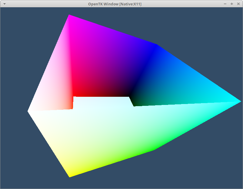
Depth Fail
These look great except sometimes everything seems inverted - what’s going on with that? We’re asking OpenGL to draw our triangles and that’s exactly what it does. Always draw every triangle. But shouldn’t some of those triangles be hidden by ones in front? That’s correct but we haven’t told OpenGL anything about that! Thankfully we can tell OpenGL to do exactly that by using a Depth Test which also thankfully only needs two changes to get working.
First we have to ask OpenGL to perform the testing by enabling it. Turning features on and off is done with GL.Enable and GL.Disable plus the required capability. If you did Chapter 1.5 you’ve already seen these in action. Our capability is fairly well named as far as code goes and is called DepthTest. Lets turn it on by itself and see what happens:
// Setup code
GL.Enable(EnableCap.DepthTest);
That doesn’t look right! Depth values are written to a texture, part of the FrameBuffer OpenTK set up for us, then read back the next time a test is performed. As with so many other things in programming the code only does what we tell it to do and we’ve only asked it to write to this buffer. Every frame is checking against the sum of all depth values written so far which results in not a lot of things being visible. We need to clear it at the start of our frame alongside the color buffer.
// loop code
GL.Clear(ClearBufferMask.ColorBufferBit | ClearBufferMask.DepthBufferBit);
As Clear only accepts one value we have to combine our two enum values with the pipe operator |. With that done we finally get to see our glorious cube in all its 3 dimensional spinning glory!
A Matter Of Perspective
If you cast your mind all the way back to What Is A Triangle? we started off by using Normalized Device Coordinates. As awesome as NDC are it’s quite a challenge to design your entire application to only use values between -1 and 1. We will use a different coordinate system where the values can cover the entire real number range and worry about how OpenGL will handle that later. This coordinate system represents the world in which everything exists and so is helpfully called World Space.
With objects happily floating about in world space we probably want to draw them using OpenGL. This is where our first coordinate transformation matrix comes in: the Projection transform. I’m not going to explain the maths beind this, although I recommend you look it up after, but skip to what it does. A Projection matrix takes a slice out of our world and transforms the values into Clip Space. To do so it requires two cutoff points: the closest part and the furthest part which are called the Near Plane and Far Plane. In between these planes it not only converts everything to our familiar -1,1 but also decides how they will look. This is also called the Projection and is typically one of two values: Orthographic or Perspective.
Despite that chunk of text we’ve barely scratched the surface of what this transform does but hopefully we know enough to put one in place. We’ll start by creating a projection matrix using a perspective projection:
// Setup code
Matrix4 projection = Matrix4.CreatePerspectiveFieldOfView(MathHelper.DegreesToRadians(90f), 1.33f, 0.1f, 100f);
We need to pass in fovy that’s the Field Of View of the Y (horizontal) value, which is one of the times I permit you to use degrees, which sets how wide a slice we take. Next is the aspect ratio which is the horizontal width over the vertical width which I am not calculating for now and will set to 1.33f which should match the default size. Finally we have the depth values our near and far planes should sit at. Remember that any values outside of these won’t be visible so we’ll use 0.1f to 100f which should easily cover our cube.
Now we have a perspective matrix we need to apply it to the position and rotation data. We’ll do that by adding another uniform to the vertex shader called projection and multiply by it when calculating the position:
#version 330

in vec3 position;
out vec3 color;
uniform mat4 rotation;
uniform mat4 projection;

void main ()
{
    color = position + vec3(0.5);
    gl_Position = vec4(position, 1.0) * rotation * projection;
}
Finally join the two up in the same way as before: fetch the uniform index and send a value to it:
// Setup code
int uProjection = GL.GetUniformLocation(shader.Id, "projection");

// loop code
GL.UniformMatrix4f(uProjection, 1, true, projection);
We can also check out an orthographic projection with its corresponding create method:
Matrix4 projection = Matrix4.CreateOrthographic(2.66f, 2f, 0.01f, 100f);
Now we have to provide the width and height of our camera which control the aspect ratio and field of view together. I’m using 2.66f an 2f to give roughly the same proportions as with the perspective. We have near and far again doing exactly the same job as before. Try changing the values and see how orthographic changes compared to perspective.
A Little To The Left
Just rotating our cube isn’t going to cut it. We also want to move and scale it - both things we can do with our matrix. To do this we’ll first update the name in the shader to transform to better match its job. Starting with the shader:
uniform mat4 transform;

// in main()
gl_Position = vec4(position, 1.0) * transform * projection;
Then back over in C#:
// setup code
int uTransformation = GL.GetUniformLocation(shader.Id, "transform");

// loop code
Matrix4 transform = Matrix4.CreateRotationX(-angle)
    * Matrix4.CreateRotationY(angle/2f);

GL.UniformMatrix4f(uTransformation, 1, true, transform);
Now we can expand our transform construction to include a Scale and Translation component. The methods are on Matrix4 like you’d expect CreateTranslation and CreateScale. There’s an important order to the combination of these transformations that ensures they get applied as expected - can you work it out? Try out a few options and see what the results are. The order is Scale, Rotate, Translate and if you remember how C# performs matrix multiplication that produces:
Matrix4 transform = Matrix4.CreateRotationX(-angle)
    * Matrix4.CreateRotationY(angle/2f)
    * Matrix4.CreateTranslation(0f, 0f, -2f)
    * Matrix4.CreateScale(1f, 1.5f, 2f);
Recap
Adding matricies to our lineup has significantly increased what our project can do. By using them to do various types of transformations we can sit in World Space and view into it with a Perspective Projection. We’ve also introduced Uniforms to send data to our shader every frame. Finally we turned on an additional capability to do Depth Tests.
With all these new tools we can transform our cube by scale, rotate and translation - in that order!
Continue with Chapter 4: A Fresh Coat Of Paint
Originally published on 2025/04/25